By Ron Beck,
Outside Technical Advisor and Manager of Training for U.S. Boiler Company
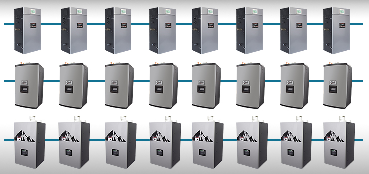
As many of you are aware, we can operate up to 8 high efficiency boilers in a lead/lag system with just a boiler enable to the master boiler and a handful of Cat-5 cables. There is much more to this story. Let’s look at other options available to U.S. Boiler Company’s high efficiency boiler product line.
Did you know there are several ways we can connect boilers to Energy Management Systems (EMS)? We can direct wire boiler demand to our TT or accept this signal over a “Modbus” communication port. We also accept a setpoint or modulation signal! Additionally, we allow the EMS to monitor a number of our status temperatures and states. Request a copy of our Modbus Interface List!
The following contains more information about our EMS interface options:
Option 1 Direct Wiring to Energy Management System (EMS)
Option 1a – EMS requires boiler demand (TT) connection:
Simply wire the contact from the EMS to the TT input on the master boiler. No other parameter changes needed. This input enables or disables all boilers connected to the peer to peer network.
Option 1b – EMS requires boiler demand (TT) and 4-20ma setpoint wired connections:
Simply wire the contact from the EMS to the TT input and a 4-20mA to our Remote Input terminals (location differs per boiler) on the master boiler. Next, go the “EMS” Adjustment Mode Menu on the touch screen display and set “Central Heat Setpoint Source” to “4-20mA”. After this is set, user may adjust “4 mA Water Temperature” and “20 mA Water Temperature” settings to desired setpoint range.
Note: The local setpoint and outdoor reset is ignored and the heating loop setpoint is set by the EMS. Now, all boilers connected to the peer to peer network will respond to the EMS setpoint and enable inputs.
Option 1c – EMS requires boiler demand (TT) and 4-20mA modulation wired connections:
Alternately, simply wire the contact from the EMS to the TT input and a 4-20mA to our Remote Input terminals (connection location differs per boiler) on the master boiler. Next, go the “EMS” Adjustment Mode Menu on the touch screen display and set “Central Heat Modulation Source” to “4-20mA”. Please note that this setting disables the local setpoint control and Sequencer Master control. These signals must be wired to each boiler individually! Individual boiler enabled and enable status and modulation rate is set by the EMS.
Note: 4-20mA input may be used for modulation or setpoint, but not both
Option 2 – EMS requires a Modbus communication connection:
Boilers may also be connected to the EMS using our RJ45 Modbus Boiler-To-Boiler Communication Network. When connecting the EMS input to the RJ45 Modbus port, the Multiple Boiler Sequencer function cannot be done by the control and must be supplied by others. Alternate supply of the multiple boiler sequencer is the EMS using Modbus or 4-20mA (as discussed above) or a third party device such as manufactured by Tekmar or Heat-timer. A Cat-5, Ethernet cable is interconnected between all boilers and directly to the EMS system. The EMS will send the information to each boiler individual and be able to monitor dozes of points on each connected boiler.
Note: RJ45 Modbus connection may be used for EMS or Multiple Boiler Sequencer, but not both.
Option 2a – EMS requires boiler demand and setpoint Modbus connections:
Simply connect the EMS to the RJ45 Modbus connection using a Cat-5 Ethernet cable. Next, go the “EMS” Adjustment Mode Menu on the touch screen display and set “Central Heat Setpoint Source” to “Modbus” and “Central Heat Demand Source to “Modbus”. Next, go the Sequencer Master Menu and ensure “Master Enable” is set to “Disable” and go to “Sequencer Slave” Menu and set a unique “Boiler Address”.
Note: The local setpoint and outdoor reset is ignored and the heating loop setpoint is set by the EMS. These adjustments and signals must be done to each individual boiler.
Option 3a – EMS requires boiler demand and modulation Modbus connections:
Alternately, connect the EMS to the RJ45 Modbus connection using a Cat-5 Ethernet cable. Next, go the “EMS” Adjustment Mode Menu on the touch screen display and set “Modulation Source” to “Modbus” and “Central Heat Demand Source to “Modbus”. Next, go the “Sequencer Master” Menu and ensure “Master Enable” is set to “Disable” and go to “Sequencer Slave” Menu and set a unique “Boiler Address”. Note: this setting disables the local setpoint control and Sequencer Master control. The boiler enable and disable status and modulation rate is set by the EMS. These adjustments and signals must be done to each individual boiler.
Note: Modbus input may be used for modulation or setpoint, but not both
Special Notes:
- Energy Management Systems are also called Building Automation Systems (BAS). Both these terms have the same meaning.
- Some EMS systems require a communication protocol that is not Modbus. For these situations, we offer Universal Gateway products. The Universal Gateway connects to our boiler’s RJ45 Modbus port and offers BacNet, Lonworks and Johnson N2 communication protocols. If the EMS needs to communicate in a language other than Modbus, you will have to purchase the Universal Gateway. Purchase the Universal Gateway LON version for Lonworks or Universal Gateway Bacnet version for all the other languages listed above.
Ron Beck is Outside Technical Advisor and Manager of Training for U.S. Boiler Company, where he’s been since 1998. Ron’s 34 years of experience in the heating industry include climbing the ranks of a HVAC company, from apprentice to service manager. Ron can be reached at: RBeck@usboiler.net

