 By Ron Beck, Outside Technical Advisor and Manager of Training for U.S. Boiler Company
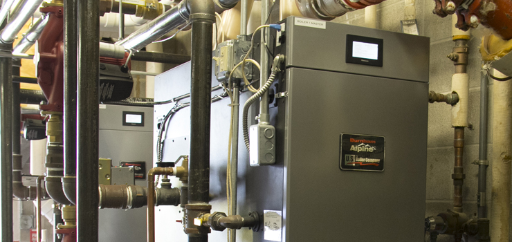
Some large homes and many commercial boiler applications will include installations of multiple boilers. The Alpine high-efficiency condensing boiler will allow up to eight boilers to be piped and wired together, all controlled by a single master boiler. The master can be any one of the multiple boilers. Each boiler requires a number, 1 through 8, including the master. This kind of installation allows contractors to offer boiler installations with turndown ratios up to 40:1.
Turndown ratio is a common phrase now, but I’m often asked, “What does turndown ratio mean,” or, “How low does the boiler turn down?” Simply put, the turndown ratio is a number that determines the minimum input. To determine the minimum input you must know two things: 1) The boiler maximum input. 2) The turndown ratio. All Alpine modulating condensing (mod/con) boilers have a 5:1 turndown ratio. If you divide the input by the turndown ratio, you can calculate the minimum input.
For example, an ALP150 is an Alpine 150,000 BTU input boiler, you would divide the 150,000 by 5 (the ratio) which would be 30,000 BTU minimum. To expand on this a bit, if you have eight, 500,000 BTU boilers, you would operate with inputs between a minimum of 100,000 BTUH and a maximum of 4 million BTUH, dependent on the load or input from an external control source, normally called – among other things – an Energy Management System (EMS).
It’s All About Control
There are two basic ways of controlling these multiple boiler applications. The easiest way is a single boiler demand to the master boiler. For an Alpine boiler, this is very simple… just add a cat-5 ethernet cable splitter to all intermediate boilers and plug an ethernet cable into each boiler to allow all the boilers to communicate to the master boiler. Add an outdoor sensor and a header sensor to the master boiler only. I prefer a well-mounted sensor or direct sensor, as opposed to a strap-on sensor, for faster reaction time. The header sensor is installed on the system piping and provides blended system and boiler water temperature information to the sequence master.
The boiler demand is a closure between the heating thermostat terminals. Any of the installed boilers appointed as a lead boiler by the master control will start and run to 50%. The master control will determine when and how many boilers are required to run to meet the set point temperature. The lead boiler will automatically rotate after 24 hours of run time (this maintains even run-times for simple maintenance). With use of the outdoor sensor, the master boiler will determine system reset temperature and maintain that temp by starting and stopping the sequential boilers.
The more labor intensive application is to run a boiler enable and a 4-20mA signal remote modulation to all installed boilers. Find the ‘Remote 4-20mA’ menu using each boiler’s touch screen. Set boiler modulation source equal to 4-20mA. The EMS can start, stop, and modulate each boiler as needed to satisfy the EMS system header sensor. In this case, the boilers are operated independently with controlled start, stop and modulation from an EMS 4-20mA signal.
The more common application I see is multiple boilers installed with only a boiler enable and possibly a 4-20mA remote setpoint signal. Install a system header sensor to the boiler chosen as the master boiler. If using the optional 4-20mA signal from the EMS to the master boiler, use the touchscreen, find the ‘Remote 4-20mA’ menu and set the ‘Setpoint Source’ to 4-20mA. When this is chosen on the touchscreen display, the next screen will ask what water temperature is required at 4mA, and the following screen will ask what the required water temperature should be at 20mA.
When wired with only a boiler demand, the master boiler will control the starting and stopping of the connected boilers to meet the required temperature on the system header sensor determined by the connected OD sensor. If there is also a 4-20mA signal and the control is set to setpoint, the master control will operate the same, except no outdoor air temperature sensor is required. The setpoint temperature is determined by the value of the 4-20mA signal. The boiler will read the system temperature through the header sensor.
We also offer a gateway to monitor the boiler operations using BACnet MS/TP, BACnet/IP, N2, Modbus TCP or LonWorks protocols. When required, only one gateway is needed for up to eight boilers, which is the maximum controlled by the master control.
Proper piping
Piping multiple boilers should use one connection point utilizing a set of closely-spaced tees or a hydraulic separator. There are dimensional rules for the distance before, after, and between the tees. A good rule is to keep the tees as close as possible and install nothing between the tees. Pipe the boilers into the branch of the tees. This piping would include a small supply and return manifold connected to the appropriate tee. Applying this application maintains higher boiler efficiency by maintaining the coolest water temperature to each boiler and only getting flow through boilers that are operating.
For complete information on these items, please see the Alpine boiler Installation and Operations Manual. The I&O manual also includes boiler pipe sizing and multiple boiler common manifold pipe sizing.
Ron Beck is Outside Technical Advisor and Manager of Training for U.S. Boiler Company, where he’s been since 1998. Ron’s 34 years of experience in the heating industry include climbing the ranks of a HVAC company, from apprentice to service manager. Ron can be reached at: RBeck@usboiler.net

